


When the rechargeable battery is connected to the load with the introduction of the capacitor, there is a surge current surge because the capacitor charges the battery voltage. The lead-in current depends on the lead-in capacitance; the larger the rechargeable battery, the stronger the load and the greater the lead-in capacitance. Large inrush current (without protective measures in the pre-charging circuit) may cause the following situations:
Import filter capacitor damaged
Assuming that the main fuse withstands inrush current without protective measures, blow the main fuse.
Due to the contact shortcomings caused by arcs and pitting caused by high surge currents (and the decline in current carrying capacity), damage to rechargeable battery cells is not suitable for surge currents.
The following is a typical pre-charging circuit for rechargeable battery operation and timing diagram, and how the flash circuit works.

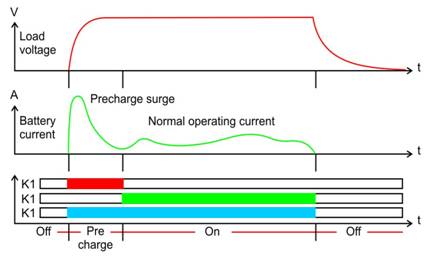
In the most basic method, the operation of the precharge circuit is as follows:
OFF: When the system is turned off, all relays / contactors are turned off.
Pre-charging: When the system is turned on for the first time, K1 and K3 are turned on to pre-charge the load until the surge current is subsided. R1 indicates the orientation of the thermistor in the precharge circuit.
ON: After pre-charging, the contactor K2 is turned on (relay K1, it is necessary to turn off to save coil power).
Select thermistor
The minimum resistance of the thermistor is determined by the following factors:
Ambient temperature
Import capacitance value (precharge circuit)
battery voltage
After the time τ = RC, the precharge surge current reaches 63.2% (1 / e) of its initial value.
When selecting the thermistor, we consider the time value of the "five time constants" when the capacitor is fully charged and the inrush current reaches the normal operating current.
For this plan, we will assume the following quantitative values:
20 ms
Temperature during environmental operation: change between 10 ° C and 50 ° C
attery voltage: 100 volts
Capacitor bank: 50,000μF
5τ = RC
R = 5τ / C = 5 (0.02 seconds) /0.05F=2.0Ω.
Query the RT curve of Ametherm thermistor at ambient and temperature of 50 ° C, flashing the material "C"
R @ 50 ° C / R @ 25 ° C = 0.412 @ R @ 10 ° C / R @ 25 ° C = 1.70
Therefore, the minimum resistance @ 25 ° C = 2.0 / 0.454 = 4.40Ω, so our standard specification parts have a nominal resistance of 5.0 ohms
At 10 ° C, the resistance of the standard specification parts is 5.0Ωx1.70 = 8.50Ω, which will meet our minimum resistance.
To admit that the thermistor needs energy for processing without self-destruction,
E = ½CV2 = ½ (0.05) (100) 2 = 250 Joules
The steady-state current is not counted, because in most pre-charge circuits, the steady-state current passes through the contactor. The part that meets your standard specification is AS325R020.
The core benefits of AmethermAS surge current limiters
Lower current density (compared to traditional inrush current limiters)
Faster reset time
Due to the lower current density and a uniform temperature gradient across the disc, there are no hot spots for fatigue
Wider operating temperature planning ithout derating